9 APR, 2026
Channel strip: pinout reference!
This is just an info-dump for me to keep reference. Read at your own risk!
This post details how each of the microcontroller's pins will be allocated to controlling the peripheral devices.
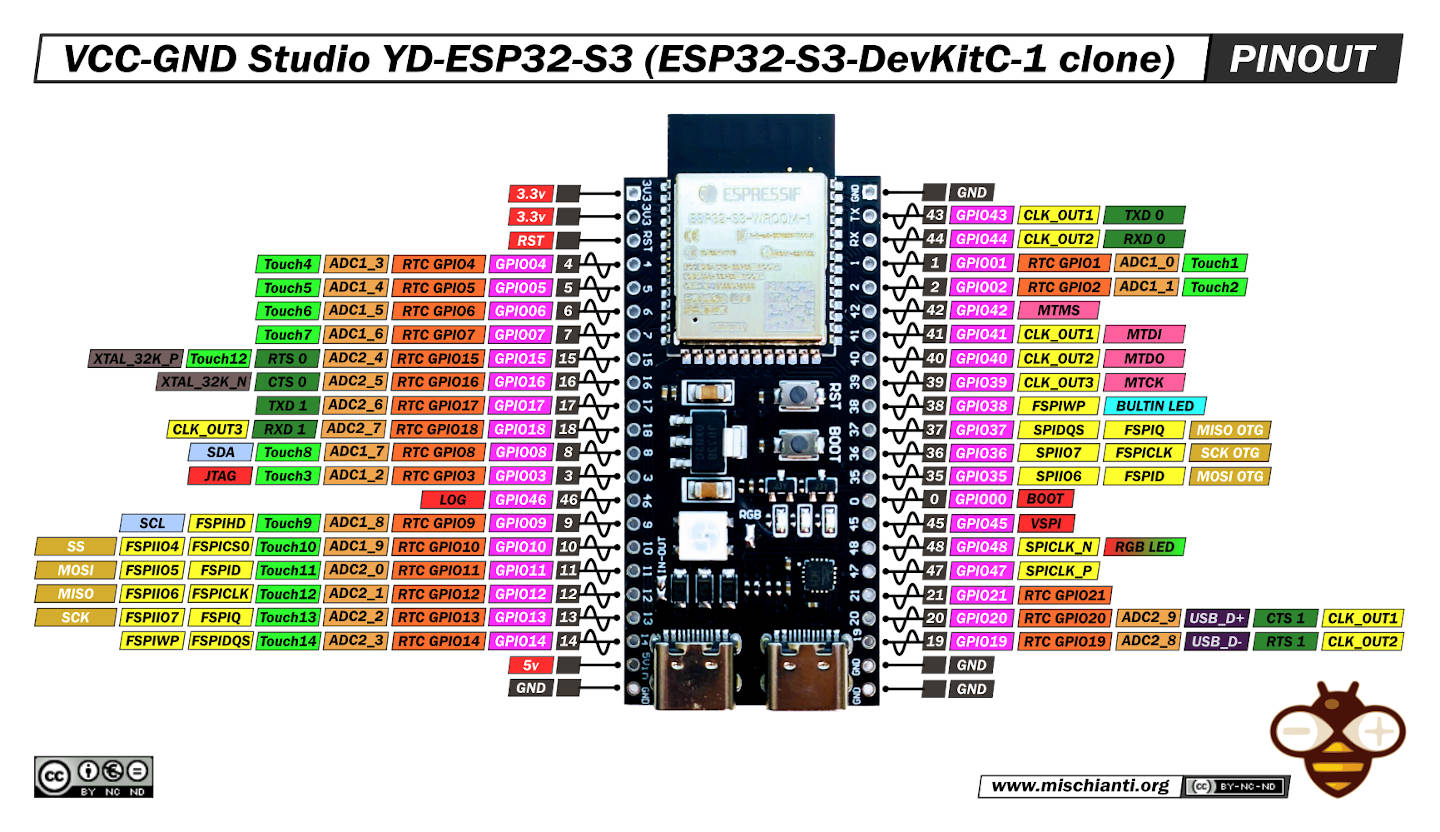
ESP32-S3
More details can be found on GitHub esp32-s3-pinouts or on the development board pinout.
| Function | Pin | Pin | Function |
|---|---|---|---|
| GPIO 43 | Motor A direction | ||
| Not connected | RESET | GPIO 44 | Motor B direction |
| Touch 1 | GPIO 4 | GPIO 1 | Encoder 1 clock |
| Touch 2 | GPIO 5 | GPIO 2 | Encoder 1 data |
| Touch 3 | GPIO 6 | GPIO 42 | Encoder 2 clock |
| Touch 4 | GPIO 7 | GPIO 41 | Encoder 2 data |
| Chip select 0 | GPIO 15 | GPIO 40 | Encoder 3 clock |
| Chip select 1 | GPIO 16 | GPIO 39 | Encoder 3 data |
| Chip select 2 | GPIO 17 | GPIO 38 | Not connected |
| Chip select 3 | GPIO 18 | GPIO 37 | MISO |
| SDA | GPIO 8 | GPIO 36 | SCK |
| Chip select 4 | GPIO 3 | GPIO 35 | MOSI |
| Fader ADC | GPIO 46 | GPIO 0 | Page left button |
| SCL | GPIO 9 | GPIO 45 | Not connected |
| WS2812 LED data | GPIO 10 | GPIO 48 | Not connected |
| Not connected | GPIO 11 | GPIO 47 | Page right button |
| Not connected | GPIO 12 | GPIO 21 | Chip select 5 |
| Not connected | GPIO 13 | GPIO 20 | Not connected |
| Not connected | GPIO 14 | GPIO 19 | Not connected |